Marble/PNTFiles
Since the beginning of the Marble Virtual Globe we've used the Microworld II Database (MWDBII) as a resource for vector data. This dataset has the advantage that it's small and can easily get shipped with Marble. One of the disadvantages has been that it hasn't been updated since 1995 and is provided in the PNT format. So far there have been no tools available to edit these PNT files. This however is especially important for editing country borders.
In order to allow editing of PNT files we've recently created a set of PNT editing tools. These allow users to modify PNT files using Inkscape. Here is an example on how to make use of these:
You need a recent checkout of the Marble Source Code and a recent version of the Qt library and its development files. For illustration we'll replace the internationally recognized boundaries of India inside Marble by those which are used on Indian official maps as an example:
First you go into the directory marble/tools/pnt2svg which is located in Marble's source code. You then need to type "qmake" and press the Enter key. Afterwards you need to press "make" and the Enter key. After successful compilation you should now have a tool that allows to convert PNT files to SVG files. You can convert a whole PNT file to SVG or just portions of it by specifying a bounding rect. The PNT file that describes the border lines for Marble is located at marble/data/mwdbii/PDIFFBORDER.PNT inside the sources. Inside the marble/tools/pnt2svg directory you can now execute the following command:
./pnt2svg -i ../../data/mwdbii/PDIFFBORDER.PNT -o world.svg
Now start up inkscape via
inkscape world.svg
And you can see all the boundaries of the world inside inkscape in full glory. But as described above we just want to change the indian boundaries. So we close inkscape again and try to limit the exported boundaries by specifying a bounding box:
./pnt2svg -i ../../data/mwdbii/PDIFFBORDER.PNT -cw 65 -ce 130.00 -cn 60.00 -cs 20.00
By default if no output file is specified pnt2svg will save the data into "output.svg". So the latest command will create an svg file called "output.svg" which contains just those boundary lines which are fully located inside the bounding box 60°N, 65°E, 130°E, 20°N. We can again open the file using inkscape by calling
inkscape output.svg
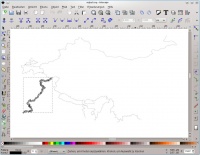
Inkscape should now show all the boundary lines around india in the specified region. In order to simplify things we now remove all the boundary lines which we don't intend to modify. This can be done by selecting those lines and pressing the "Del" key on the keyboard. If you accidently remove too much then you can always undo the deletion.
Once you have just one or two lines left you can save your work already. Before you save it's absolutely necessary that you adjust the Inkscape settings: Go into "File->Inkscape Preferences". Look for "SVG Output" on the left and uncheck "Allow relative coordinates" and check "Force repeat commands".
If you look at the saved file with a text editor there should only be very few (one or two) "path" xml tag elements inside the file.
Now we continue our work in Inkscape: By pressing "F2" inside inkscape we can switch into "Edit paths by nodes mode.". In this mode you can easily move nodes, delete nodes and add nodes to the existing paths. If you don't know how to do this there are a lot of Inkscape Tutorials that will teach you how this works. While modifying your path just make sure that you don't convert your linestring segments into curves (since the PNT format doesn't support those).
In our example we just move the nodes and border lines a bit to match the desired shape. You could import a (properly licensed) bitmap map as a "template". Note however that the map you import needs to be in "Equirectangular Projection" / "Plate Carree Projection". Once you are done, save your work. Open up the SVG file with a text editor. Inside you'll still find the path xml elements. Look for a string that looks like this (just with other numbers): id="path62_9083". You need to remember your path id for later use. The second number (here: "9083") resembles the header id in the PNT file.
Now we want to replace the original paths with our modified versions. In order to do this we need the pntreplace tool. Just like with "pnt2svg" we go into the directory marble/tools/pntreplace and we call "qmake" and "make" there. Now our tool is ready for use. We now call:
./pntreplace -i ../../data/mwdbii/PDIFFBORDER.PNT -o TEST.PNT -s ../pnt2svg/output.svg -id 9083 -path path62_9083
This will create a new PNT file called "TEST.PNT" which has the boundary with the PNT header id "9083" replaced by the path "path62_9083" from our modified SVG file. You can now copy the file TEST.PNT over into your system directory (be careful and note that your system directory will likely be a different one!)
sudo cp TEST.PNT /usr/local/share/apps/marble/data/mwdbii/PDIFFBORDER.PNT
and then restart Marble. The modified line should appear now. Note that if you want to replace a second line in addtion then you need to call the pdfreplace tool on the modified TEST.PNT file! This could be done like this:
./pntreplace -i TEST.PNT -o TEST2.PNT -s output.svg -id 9063 -path path48_9063
and afterwards you could copy the result over into the marble system data directory:
sudo cp TEST2.PNT /usr/local/share/apps/marble/data/mwdbii/PDIFFBORDER.PNT
Once done you can start Marble again and enjoy your newly modified PNT file.
In addition to the tools mentioned there are also two other ones: svg2pnt which converts a whole svg (with proper canvas size) to a pnt file or appends it to an existing one. And there is pntdel that allows to delete polylines with a certain PNT header id from an existing PNT file.

